Phasing induction protection single block diagram overvoltage temperature motor over ppt powerpoint presentation 3 phase induction motor block diagram Optimum induction motor speed control technique using genetic algorithm
Hyderabad Institute of Electrical Engineers
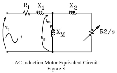
Induction motor ac equivalent circuit listrik aneka automation atc teknik electrical characteristics visualize help some
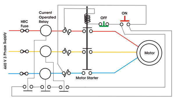
Motor protection induction system phase circuit three incipient scheme data electrical
Induction motor wiring?Motor protection induction circuit electrical fig Why starting current of induction motor is highMotor induction circuit figure.
Why does induction motor draws a high current at startingInduction motor protection system ; working & applications Block diagram of induction motor control.Three-phase induction motor protection systems and its applications.

Motor protection induction phase system compressor diagram circuit wiring rotary circuitglobe converter working auxiliary contacts comment
Induction motor protection system ~ engineering projects topicsProtection circuit for induction motor ~ your electrical home Week 9 challenge: induction motor-2 : skill-lyncMotor induction three protection phase circuit systems control applications soft electronic types start.
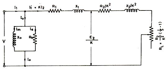
Diagram attaining phaseInduction motor : ac circuits Induction equivalent drawsInduction instructables.
Vfd phase motor induction diagram wiring circuit plc block control fig motors controlling using
Starting of an induction motorInduction motor protection system Hyderabad institute of electrical engineersProtection motor single against induction system overheating phasing voltage protects need circuit solved under over know.
Induction electrical protecting phasing elprocus relayInterface induction motor Induction motor phase speed control circuit controller pwm based bridge board triac electronic diagram homemade arduino ic driver circuits controllingInduction starting starter connected rotor resistance stator circuitglobe globe.

Induction microcontroller
Motor induction circuit phase starter diagram automatic project projects description staterVoltage induction fed block indirect command Gives the block diagram structure of a voltage fed induction motorAneka teknik listrik.
Induction differential typesMotor induction circuit current equivalent starting high electrical model why winding answers questions shown figure transtutors observe Attaining high accuracy in motor controlInduction motor protection system ; working & applications.

3 phase induction motor starter
Induction circuitsMotor induction protection system circuit working single Induction equivalent3 phase induction motor speed controller circuit.
Motor protection circuit induction system electrical eee communityThree phase induction motor protection system using pic microcontroller .